How to orientate a part as we wish
Use the  "Snap View" tool to get a front view of a selected face or plane. You can also use the tool to move the highlighted face or plane to the top, bottom, right, or left.
The  "Snap View” tool works on objects with one direction: planes, references, cones, toroidal shapes, curves and edges. For nonlinear curves, the direction between two ends determines the direction.
This tool can only be used in 3D mode and it is disabled with Sketch and Section modes.
Click on
 "Select" or press "S".
Click on
 "Snap view" in the group Orient inside Assembly tab.
Use the objects in the Design window to orient the view
Select face and frame it
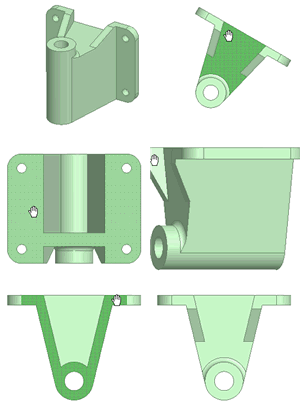
Click and release on a plane, point, cone, toroidal shape, curve, or edge. If the object does not show a frontal orientation, it will rotate until the selected face is seen frontally, like this:

If the object is already shown from the front, it will rotate 90 ° counterclockwise so that it is framed in the Design window, like this:

Change view
Click, drag, and drop a plane, cone point, torus, curve, or edge to flip it up, down, right, or left. If the object does not show a front orientation, it will rotate until the selected face is viewed frontally and is framed in the Layout window, like so:

If the object is already displayed head-on, it will rotate 90 ° in the direction of its drag, as shown below:

Rotating the display
Click on any empty space to rotate the view 90° counterclockwise, like this:

Repeat until you get the desired view.
This trick will help us to better orient ourselves in the part when we are designing or machining.

Rotation display
